The Main Window is the central control for using the DPS Profile Creator. Closing this window quits the DPS Profile Creator application.
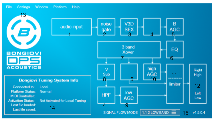

The audio processing signal flow is represented in the Main Window.
TIP: Click a block on the signal flow diagram to open its control window.
- Audio Input – Represents audio going into the DPS processor. Click to open Meters and Analysis window.
- Noise Gate – For creating a better signal to noise ratio.
- V3D, Dynamic Stereo, and other special effects – The patented Bongiovi Dynamic Stereo speaker enhancement algorithm, V3D for headphones, and Karaoke blocks always occur first in the DPS signal path so the Bongiovi AGC and other adaptive blocks can smooth and enhance the special effects.
- High Pass Filter – For removing unwanted low frequencies. When Virtual Subwoofer is enabled, this block moves to the end of the signal path to control newly generated low frequencies.
- Bongiovi Automatic Gain Controller (AGC) – Controls dynamic range based on frequency content. When in 3 Band AGC mode, the Bongiovi AGC may be switched from the beginning of the signal path (default) to the middle band. This allows for 3 band speaker protection.
- Equalizer – 10 bands of mastering quality parametric IIR bell filters.
- Crossover – Used to split audio into 1, 2 or 3 frequency bands.
- Virtual Subwoofer – Used to dynamically generate big bass for small speakers.
- Low Frequency AGC – Used to control dynamic range of low frequencies.
- High Frequency AGC – Used to control the dynamic range of high frequencies.
- In ARM Low Only AGC mode, this block is used as a full band AGC after the low AGC and high bands are summed.
- Limiter – Used to prevent clipping of signals approaching 0dBFS. When in 1.1 speaker mode, separation of the bands into High and Low is indicated by the – – – – line.
- Available in Analog Modeling or Look-Ahead modes.
- Only Look-Ahead mode is available for ARM/NPCA12x platforms.
- Available in Analog Modeling or Look-Ahead modes.
- Audio Output – Represents final audio leaving the DPS processor including Output Gain. Click to open the Meters and Analysis window.
- B Button Logo – Click to bypass or enable DPS processing.
- Tuning System Information – Displays useful information about the current tuning hardware and software environment.
- Signal Flow Mode
- Default is the standard stereo or mono DPS signal path shown in the diagram.
- 1.1 speaker modes divide the DPS blocks into high (usually right channel) and low (usually left channel). The low channel uses EQ bands 1-4 and does not use the Bongiovi AGC. The High channel uses the Bongiovi AGC and EQ bands 5-10.
- The modes are further separated into 1 low AGC band (which gives 2 high bands) or 2 low AGC bands (with one high band) for best flexibility when tuning small speaker systems.
- Separation of the bands into High and Low is indicated by the – – – – line in the Limiter block.
- 2.1 Mode – The output of the Low-Frequency AGC is sent to the subwoofer output channel if available on the connected platform.
- The Output Gain of the low-frequency AGC (9) controls the output of the subwoofer channel.
- See Parameter Window for more information about controlling the subwoofer channel when in 2.1 mode.