- This document refers to the DPS library running on the NUC505 ARM M4 processor only.
Initialization
DPS_GlobalInitialize must be called first. The function will return 0 when initialization is successful.
Function Declaration:
uint32_t DPS_GlobalInitialize(void);
Example Initialization:
 err = DPS_GlobalInitialize();
 if (err > 0)
 printf("Initialization Error");
Parameter Loading
DPS_LoadPreset is used to load a DPS parameter set from the indices.c file. Accepted values are:
- 0 = Profile 1
- 1 = Profile 2
- 2 = Profile 3
- 3 = Profile 4
- 4 = Default Flat Profile – The DPS process is engaged but there is no audio effect. User Controls will function normally.
Function Declaration:
void DPS_LoadPreset(uint8_t N); // N = 0, 1, 2, 3, or 4
Example:
DPS_LoadPreset(1); // Load Music Demo Profile #2
DPS_parse_byte is used to interpret serial commands from UART for the DPS Profile Creator. It is very important this feature is working so the audio engineer can use the DPS Profile Creator to adjust the DPS algorithm for the audio device.
Function Prototype:
void DPS_parse_byte(uint8_t rxword);
This function will return or set parameters depending on input values.
Example:
void UART0_IRQHandler(void)
{
 uint8_t x;
 uint32_t u32IntSts = UART0->INTSTS;

if(u32IntSts & UART_INTSTS_RDAINT_Msk)
 {
 x = UART_READ(UART0);
 DPS_parse_byte(x);
 }
}
Important Serial Commands
The serial communication is basically structured this way:
{START BYTE, FUNCTION BYTE, PARAMETER BYTE, VALUE BYTE}
This UART command below sets control parameter N to value V:
{0xff (START), 0xfe (SEND TO PARAMETER), parameter N (PARAMETER INDEX), value V (INTEGER VALUE)}
After connecting the DPS Profile Creator (v1.0.0b7 and later) to the NUC505 Audio Board, you may view all serial data sent and received in the Serial Debug Window:
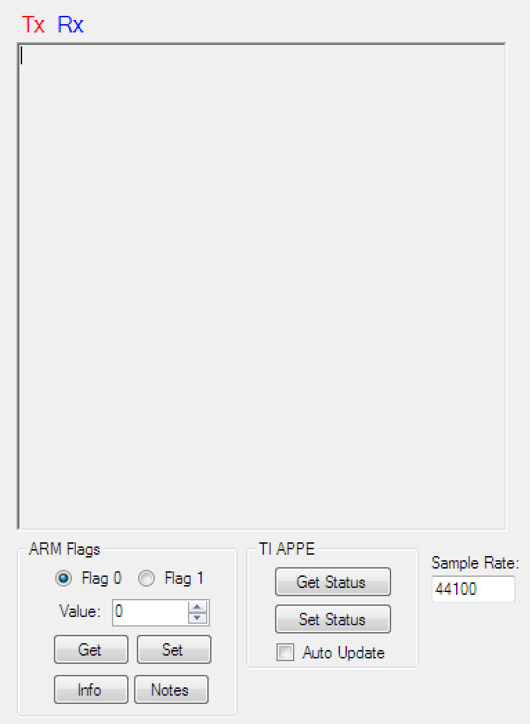
TIP: Click and move each control in the User Controls window to see the serial control parameter and value ranges. Use this serial data to assist creation of UART DPS controls for your application.
Click Info to get firmware details. Click Notes to see information about the profiles in indices.c.
{0xff, 0xfc, parameter N} — Return the current value of parameter N via UART connection.
{0xff, 0xfa, preset #N} — loads preset (DPS Profile) #N (N = 0, 1, 2, 3, 4} from indices.c.
{0xff, 0xfb} — Returns the value of every parameter, in order, terminated by 0xff. This is sent during initial connection with the DPS Profile Creator. If a proper series of bytes is received, the serial connection is considered successful. If the proper bytes are not received a connection error is reported. The serial connection must then be re-established in the DPS Profile Creator.
{0xff, 0xf9} — bypasses DPS
{0xff, 0xf8} — enables DPS
{0xff, 0xf7} — bypasses stereo widening
{0xff, 0xf6} — enables stereo widening
Input/Output Meter Calculation
Calculating the index value for input and output meters uses CPU resources on the ARM processor. This feature is disabled by default. When the feature is enabled, input and output level information is available upon request by the DPS Profile Creator via DPS_parse_byte.
void DPS_EnableLevelMeters(void); // enables computation of input and output levels
void DPS_DisableLevelMeters(void); // disables computation of input and output levels
User Controls
NOTE: The index ranges for the User Controls described below also apply to UART serial communication.
Bongiovi DPS Processing Enable/Bypass
void DPS_EnableDPS(void); // turn on DPS
void DPS_BypassDPS(void); // turn off DPS
Stereo Enhancement (Stereo Widening) Enable/Bypass
void DPS_EnableStereoWidening(void); // turn on stereo widening (simple or normal -- whichever is active)
void DPS_BypassStereoWidening(void); // turn off stereo widening (simple or normal -- whichever is active)
User Volume Control
void DPS_SetUserGain(uint8_t value); - set user gain to index "value"
The UserGain is a volume attenuation function.
User Volume Control range is 0dB (maximum) to -80dB (minimum) in 0.5dB steps.
index 160 = 0dB (max volume)
index 158 = -1dB
index 0 = -80dB (minimum volume)
User EQ (Bass and Treble)
User EQ Frequency
void DPS_SetUserEQ_Fc(uint8_t whichEQ, uint8_t value); // set user EQ center frequency to index "value" (whichEQ = 0, 1)
uint8_t DPS_GetUserEQ_Fc(uint8_t whichEQ); // get user EQ center
frequency (whichEQ = 0, 1)
DPS_Get/SetUserEQ_Fc indexes this array:
FcArray = {28.0, 31.0, 35.0, 40.0, 45.0, 50.0, 56.0, 63.0, 70.0, 80.0, 90.0, 100.0, 112.0, 125.0, 141.0, 160.0, 180.0, 200.0, 225.0, 250.0, 280.0, 315.0, 350.0, 400.0, 450.0, 500.0, 560.0, 630.0, 700.0, 800.0, 900.0, 1000.0, 1120.0, 1250.0, 1400.0, 1600.0, 1800.0, 2000.0, 2250.0, 2500.0, 2800.0, 3150.0, 3500.0, 4000.0, 4500.0, 5000.0, 5600.0, 6300.0, 7000.0, 8000.0, 9000.0, 10000.0, 11200.0, 12500.0, 14100.0, 16000.0, 18000.0, 20000.0};
Frequency range is 20Hz to 20000Hz
0 = 28Hz
31 = 1000Hz
57 = 20000Hz
Use 160Hz (index 5)for normal Bass control.
Use 5000Hz (index 45) for normal Treble control.
User EQ Quality Value
void DPS_SetUserEQ_Q(uint8_t whichEQ, uint8_t value); // set user
EQ Quality factor to index "value" (whichEQ = 0, 1)
uint8_t DPS_GetUserEQ_Q(uint8_t whichEQ); // get user EQ Quality
factor (whichEQ = 0, 1)
DPS Get/SetUserEQ_Q indexes this array:
QArray = {0.4, 0.5, 0.6, 0.7, 0.8, 0.9, 1.0, 1.2, 1.4, 2.0, 2.5, 3.0, 4.0, 5.0, 6.5, 8.0};
Q range is 0.4 to 8.0
0 = 0.4
6 = 1.0
15 = 8.0
Use Q value of 0.7 for normal Bass and Treble control.
User EQ Gain
void DPS_SetUserEQ_G(uint8_t whichEQ, uint8_t value); // set user
EQ gain to index "value" (whichEQ = 0, 1)
uint8_t DPS_GetUserEQ_G(uint8_t whichEQ); // get user EQ gain
(whichEQ = 0, 1)
DPS_Set/GetUserEQ_G indexes this gain array:
GainArray = {0.251189, 0.266073, 0.281838, 0.298538, 0.316228, 0.334965, 0.354813, 0.375837, 0.398107, 0.421697, 0.446684, 0.473151, 0.501187, 0.530884, 0.562341, 0.595662, 0.630957, 0.668344, 0.707946, 0.749894, 0.794328, 0.841395, 0.891251, 0.944061, 1.000000, 1.059254, 1.122018, 1.188502, 1.258925, 1.333521, 1.412538, 1.496236, 1.584893, 1.678804, 1.778279, 1.883649, 1.995262, 2.113489, 2.238721, 2.371374, 2.511886, 2.660725, 2.818383, 2.985383, 3.162278, 3.349654, 3.548134, 3.758374, 3.981072, 4.216965, 4.466836, 4.731513, 5.011872, 5.308845, 5.623413, 5.956622, 6.309574, 6.683439, 7.079458, 7.498942, 7.943282};
The range is -12dB to +18dB in 0.5dB increments.
0 = -12dB
24 = 0dB
60 = +18dB
Use range -6dB (index 12) to +6dB (index 36) for normal Bass and Treble control.
This is a good tool for calculating decibel value of a scalar float
Audio Processing
The audio processing functions must be performed in the following sequence:
1 – Noise Gate
Low-level noise must be eliminated from the signal. This is always most effective when done first in the processing chain.
void NoiseGateProcess(float32_t *data_L, float32_t *data_R); // run noise-gate process on stereo left and right audio buffers
2 – Stereo Enhancement
It is recommended Stereo Enhancement is performed second. Any frequency shifts will be handled un the DPS process that comes next.
There are two Stereo Enhancement modes:
Dynamic Stereo Enhancement – This function contains an AGC that controls the amount of enhancement. This ensures maximum enhancement always takes place while important center channel information is preserved.
void StereoWiden(float32_t *leftBuffer, float32_t *rightBuffer); // run stereo-widening process on left and right audio buffers
Simple Stereo Enhancement – This function does not contain an AGC. The amount of stereo enhancement is fixed to the value set in the DPS Profile Creator. Also, if this method is used, the stereo enhancement meters will not move in the DPS Profile Creator.
void SimpleStereoWiden(float32_t *leftBuffer, float32_t *rightBuffer);// run simplified stereo-widening process on left and right audio buffers
The StereoExpand function is used to automatically switch to SimpleStereoWiden when the NUC505 is set to 48kHz sample rate. Learn more about this here.
void StereoExpand(float32_t *leftBuffer, float32_t *rightBuffer); // automatically switches to simplified Stereo Widening when at 48k sample rate
3 – DPS Dynamics and Equalization
Third, the main DPS algorithm (AGCs and Equalizers) is applied to smooth the effects of the Stereo Enhancement and provide an optimized audio signal for the speakers:
void DPS_Left(float32_t *audioBuffer); // run DPS process in-place on left-channel audio buffer
void DPS_Right(float32_t *audioBuffer); // run DPS process in-place on right-channel audio buffer.
1.1 Speaker Mode
It is now possible to control bi-amped low and high frequency drivers separately using the DPS algorithm. Instead of DPS_Left and DPS_Right, use the new 1.1 processing API:
void DPS_1Pt1_Low(float32_t *audioBuffer); // run DPS 1.1 speaker process on low channel audio buffer
void DPS_1Pt1_High(float32_t *audioBuffer); // run DPS 1.1 speaker process on high channel audio buffer
NOTE: DPS Profile Creator provides a selection on the Main Window to switch from Default to 1.1 modes. This switch will change 1.1 modes but you must use the 1Pt1 API shown above in your ARM code to hear the effect.
In 1.1 speaker mode the algorithm has these features:
- 1 low band or 2 low band ouput AGC options are available.
- Low channel uses EQ bands 1-4
- High channel uses EQ bands 5-10
4 – Small Speaker Settings
The Bongiovi AGC may now be changed between input or output on the mid band. Moving the Bongiovi AGC to Output creates a 3 band DRC with best possible sound on small speakers. This parameter is set by the DPS Profile Creator and saved into indices.c but it may also be set by the ARM API:
DPS_SetBongioviAGCInput(uint8_t mode); // 0=input, 1=output
When using the 1.1 audio processing API, you may switch AGC modes with this API. This setting is also saved in indices.c:
void DPS_Set_1Pt1_Mode(uint8_t mode); // 0 = 1 low band, 1 = 2 low bands
To better calibrate the performance of a small speaker at max volume, it is useful to clip the signal to prevent fast transients from moving the speaker too much. Use this API to calibrate the clipping mode and threshold:
void DPS_SetOutputClipMode(uint8_t mode); // 0=bypass 1=hard clip 2=soft clip
void DPS_SetOutputClipThreshold(float32_t thresh); // set output clipping scalar value 1.0f = default = 0dBFS 0.5f = -6dB
5 – Headphone Effects
Two headphone effects are available:
- Version 1 Headphone Effect
The version 1 headphone effect efficiently generates a simple 3D effect for any headphones. It is currently used in several gaming headsets on the market. This function is used by calling it’s processing function in the audio buffer loop:
void doHeadphones(float32_t *leftBuffer, float32_t *rightBuffer); // run Headphone effect process on left and right channels
- Version 2 Headphone Effect = V3D
V3D is the premier Bongiovi headphone effect. For stereo sources, it is considered to be “virtual 7.1” as it creates the effect of true surround sound. It is provided in a separate library. See V3D.h for API details. This function is used by calling it’s processing function in the audio buffer loop:
void V3DProcessChannels(float32_t* leftBuffer, float32_t* rightBuffer, int numFrames);
Both versions use the same 0-6 preset format:
//   Headphone Stereo Enhancement Controls
void setHeadphones(int which); // Set V3D Headphone Effect mode which = 0,1,...,6 index
/********
		Headphone Enhancement Preset Index
			   Preset Index
			   0 = Wide Normal
			   1 = Wide Expanded
			   2 = Middle Clarity
			   3 = Middle Clarity Expanded
			   4 = Mono
			   5 = Stereo Enhance
			   6 = Stereo Enhance Max
********/
void setHeadphoneDelay(int del); // Set Headphone Effect delay value in del = 1,...,6  samples //
VERSION 1 ONLY
void setHeadphoneBypass(int bp); // 1 = bypassed 0 = enabled